Atari Punk Console
"Das Atari Punk Boxen"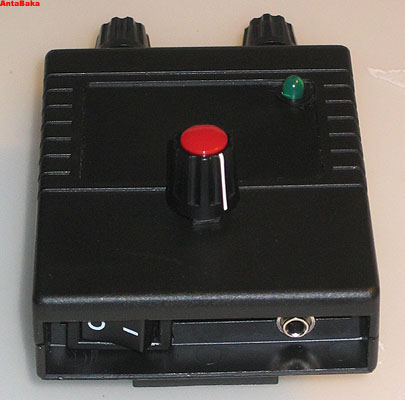 |
"C64 Punk Box"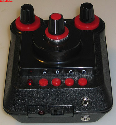 |
|---|
"Das Atari Punk Boxen" |
"C64 Punk Box" |
|---|
The Atari Punk Console (called APC from now on) is based on a circuit by Forrest M. Mims, III., which has been published in his book "Engineer's Mini-Notebook - 555 Circuits" already in 1984. It is a very simple circuit which uses only one IC (a 556 dual timer), two potentiometers, three resistors and three capacitors. All in all just 9 components.
Technically this thing consists of one astable oscillator (the first timer) driving a monostable oscillator (the second timer), creating a square waveform. Since the 555 basically consists of two 555 timers, we only need the 556. Alternatively you could use two 555 of course.
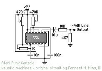
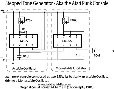
Picture: The basic circuit for the APC as a 556 version and as a 555 version.
(Source: Schema #1 von Kaustic.net, Schema #2 von Rob the Fiddler)
Ah right - the name for the APC comes from the fact that it creates sounds which resemble the sounds of the first video game generation, which explains the "Atari" portion of the name. The "Punk" part comes from the idea that it creates wild sounds - real bleepy-bloopy-gitchyness.
To actually get this sound and hear it, we need to expand the above circuit with an audio jack. Maybe add a volume control. And possibly a LED to see if it is powered on. Which brings us to the circuit created by Matthew Helm (Worth_Ekik).
One comment to the circuit: The resistor R4 is too big at 1k Ohm if you use a 9V batterie for the current - the LED is barely visibly alight. I therefore added a 562 Ohm resistor in parallel, resulting in ~350 Ohm and the LED is nicely lit. Of course it would be best to use a 390 Ohm resistor right away instead of soldering two resistors.
Picture: The complete circuit by Matthew Helm.
(Source: ©2006 Matthew Helm (Worth_Ekik))
First I had to gather all the needed components:
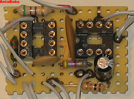
When creating the actual board I followed closely to the original layout plan, however I made sure to stick all components tightly together, since I was unsure if all the stuff would actually fit into the rather small casing. As it happened, I had to re-solder the ELKO sideways instead of upright to make it fit after all.
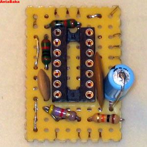
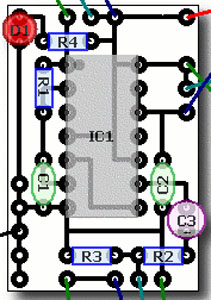
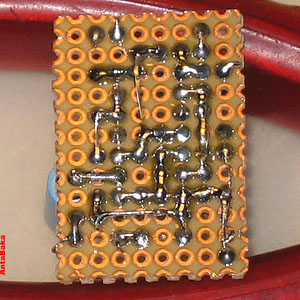
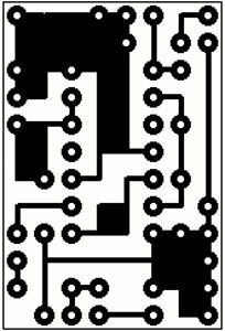
Picture: The completed board (without connection cables) in comparism with the layout (solder side of the layout mirrored).
(Source: Layouts ©2006 Matthew Helm (Worth_Ekik))
Now I did the first fit in test (sadly too late) and discovered that I had to resolder the ELKO (see above). The rest fit in just nicely. The module already had markings for the two upper potentiometers (usually one had switches and buttons there). For the 'hidden' switch and the also 'hidden' audio jack I had to cut away some plastic from the lower part to make it fit. One hole for the volume control potentiometer and the LED needed to be cut as well.
  |  |
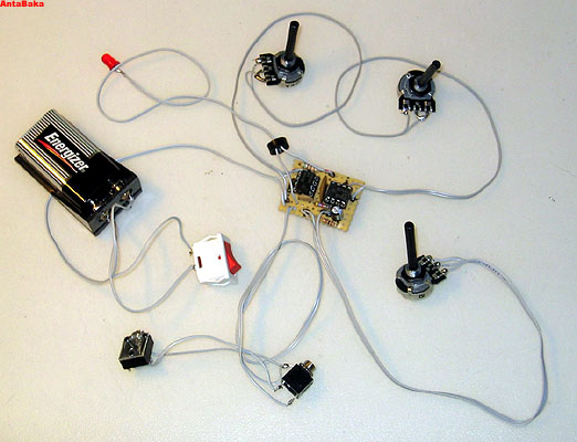
Next up were the cables to the external components. All potentiometers, the switch, the LED, the audio jack and the battery holder needed to be connected to the actual board. After the first test I corrected the 1k Ohm resistor as described above and was ready to close the case, so to speak.
Picture: Everything connected and battery holder screwed to the backside.
Yep. Now just take off some of the length from the potentiometers and add the knobs and the cookie crumbled. Next up would probably a nice logo sticker for the pre-destined field in the front but that would finish it.
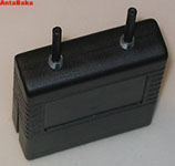
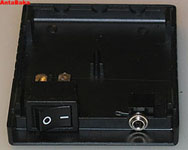
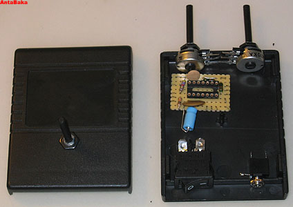
Picture: The whole piece from the front and the back and a view to the 'hidden' components.
Well, one could add two turn-switches (6-point) to it, which select different capacitors for C1 and C2.
Example values:
| For C1 and C2 | Value | Type |
|---|---|---|
| 0,01 uF | Ceramic | |
| 0,047 uF | ||
| 0,1 uF | ||
| 0,47 uF | ||
| 1,0 uF | Electrolytic | |
| 5,0 uF |
One could also use optoresistors instead of the potentiometers to create sound by light or any other kind of resistor value driver (pressure, other sound, etc).
If you keep on adding stuff you end up doing ad Sound Effekt Generator, which is also based on the 556, but would not be considered a pure APC.
In the field of sound generation (LoFi) there is a lot of info on the web. If you are interested then check out the links below and browse the websites.
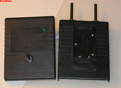
Ich habe mich dann doch noch an eine 2x 555er Version gemacht. Die Teileliste ist eigentlich identisch mit der Ein-Chip Version, nur statt dem 556 braucht man zwei 555er. Ein GehÄuse hatte ich noch von einer anderen Bastelaktion übrig, bei der ich eine C64DTV Konsole in eine PSone-GehÄuse verfrachtet habe. Ich habe diesmal sowohl eine Mono-Audio-Buchse als auch eine Stereo-Buchse eingebaut (wenn ein Stecker in der Mono-Buchse steckt, dann ist die Stereo-Buchse abgeschaltet). Ausserdem kam das GehÄuse bereits mit einem Batteriefach für 4x1.5V Batterien, daher konnte ich den 9V-Block und die halterung weglassen.
Als Vorlage habe ich diesmal den Bauplan von Seljer basierend auf dem Schaltplan von J. Anderson (jeweils in diesem Thread auf diystompboxes.com genommen. Der Bauplan war allerdings fehlerbehaftet, daher habe ich ein paar Korrekturen und ErgÄnzungen (Audio-Buchse, Betriebs-LED) vorgenommen. Nachdem ich das Ding gebaut hatte, habe ich den Bauplan nocheinmal optimiert, da ich viele Anschlüsse etwas durcheinander gelegt hatte.Daher sind die Platinenansichten und die BauplÄne nicht ganz deckungsgleich.
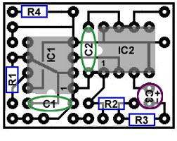
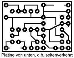
Bild: Bauplan für die Variante mit zwei 555ern, Bestückungssicht und Lötseite.
(Quelle: Selbst erstellt, basierend auf Schema und Bauplan von Seljer und J. Anderson.)
Wie üblich ging es spÄt nachts mit dem Arbeiten los. Bis 2:30 Uhr war ich mit der Platine fertig und bin erstmal in's Bett.
Am nÄchsten Morgen habe ich erstmal alles miteinander verbunden und getestet.
  |  |
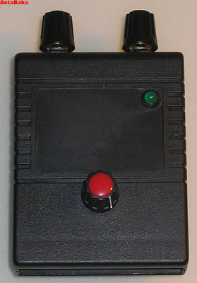
Am GehÄuse war wenig zu tun - ein paar Knöpfe ankleben, die Button mit dem Dremel bearbeiten, damit die Potis reinpassen und ein österreichisches 2 Groschen-Stück durchbohren als Abstandshalter für den LautstÄrkeregler (hatte grad nix anderes zur Hand). Die Buttons sind zweckfrei, da keine Anschlüsse darunterliegen. Der Reset-Button wurde zur Power-LED umgebaut, da ich den original Anschalter zunÄchst nicht gefunden habe.
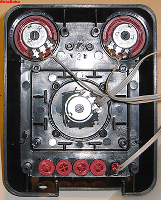
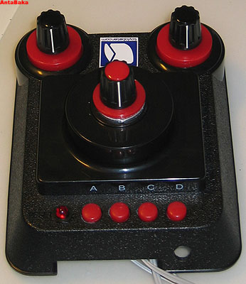
Bild: Der Deckel von innen und aussen.
Und mal wieder fertig.
NÄchste Woche dann der VerstÄrker dazu, denn im Moment kann man nur über Kopfhörer oder VerstÄrker was damit anfangen.
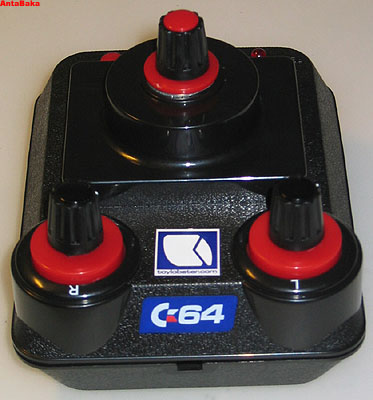
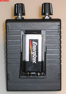
Bild: Die fertige C64DTV Punk Boxen.
Die LautstÄrke der Atari Punk Console ist gerade laut genug, um über Kopfhörer gut hörbar zu sein. Eine Ausgabe über externe (passive) Lautsprecher ist dabei nicht möglich. Daher habe ich einen kleinen VerstÄrker gebaut. Und da in dem GehÄuse noch perfekter Platz für einen Lautsprecher war, habe ich diesen gleich mit eingebaut.
Um den VerstÄrker zu bauen benötigen wir nur wenige Bauteile:
Mit den Teilen und der Schaltung lÄsst sich ein einfacher VerstÄrker mit sagenhaften 0.325 Watt bauen. Das Wunderwerk ist dabei der LM386 von National Semiconductor. Der Chip kann zwischen 20 und 200x VerstÄrkung liefern. Der ELKO zwischen Pin 1 und 8 sorgt in der vorliegenden Schaltung für 200x, lÄsst man diesen weg, so sind es 20x. Schaltet man einen 1.2k Ohm Widerstand in Reihe mit dem ELKO so sind es 50x (s. Datenblatt des Chips).
Bild: Der Schaltplan und der Bauplan.
Quelle: Schaltplan von benes elektronikseiten, Bauplan selber erstellt.
Doch zunÄchst einmal baue ich das ganze Ensemble auf einem Breadboard testweise zusammen. Dies ist das erste Mal für mich, das ich ein Breadboard benutze und ich muss sagen - das ist sehr praktisch.
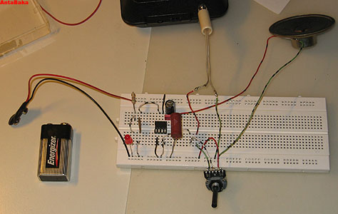
Bild: Der Testaufbau auf dem Breadboard.
Quelle: Schaltplan von benes elektronikseiten.
Auf dem Breadboard funktioniert alles prima - damit kann ich an die zweite Phase gehen: Die Bestückung der Platine. ZunÄchst habe ich einen bauplan gemalt (s.o.), um möglichst wenig Platz zu verwenden. Dies hat sich spÄter audgezahlt (siehe die Detailansicht weiter unten). Als Tool habe ich den (DIY Layout Creator) verwendet. Eine optimale Lösung gibt es natürlich nicht, aber ich war mit meinem Aufbau sehr zufrieden.
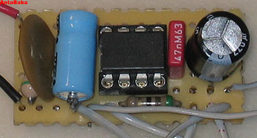
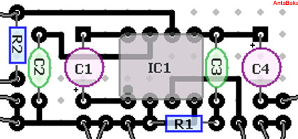
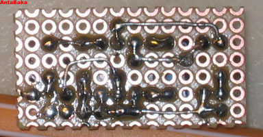
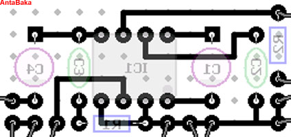
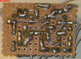
Bild: Bestückungs- und Lötseite jeweils mit Plan (Lötseite gespiegelt).
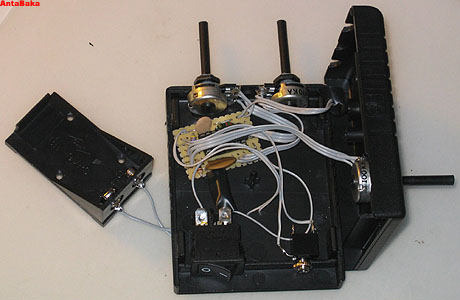
AufrÄumen und einpassen. Meine Knauserigkeit, wenn es um die Platinenbestückung geht, hat sich bewÄhrt: Sowohl der Atari Punk Teil als auch der VerstÄrker passen in die hinteren Aussparungen des GehÄuses. Der Lautsprecher wird innerhalb des GehÄuses eingebaut, da dort jetzt genügend Platz ist. Dafür fliegt die Stereobuchse raus - den Platz brauch ich für den An-/Aus-Schalter des VerstÄrkers zum Stromsparen, wenn ich per Kopfhörer arbeite. Apropos Kopfhörer: Das Einstecken des Kopfhörers unterbricht die Ausgabe über Lautsprecher. Dies gibt dem VerstÄrker genug Platz und der Magnet kommt nicht in die Quere.
Damit sind wir wieder fertig - das GehÄuse sieht von aussen aus wie vorher und nur ein kleiner Kippschalter verrÄt, dass dort ausser der Ataric Punk Console noch etwas im GehÄuse sitzt.
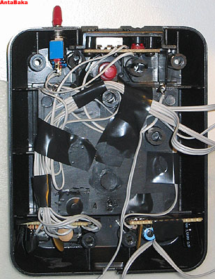
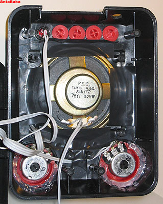
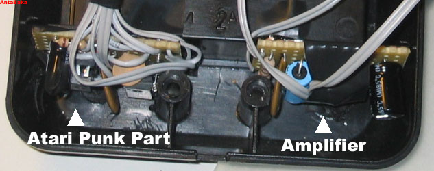
Bild: Die untere und die obere HÄlfte der Punkbox. Detailansicht mit der Elektronik.
Links to more information about APCs and LoFi Stuff:
Links to more information about the LM386 Amplifier:
Last update: 25.02.2007, AntaBaka