Almost a year ago I bought one of these C64DTV joysticks. The first reason was that I grew up with the C64 (it was my first computer) and I still own a few boxes with stuff for it. The second reason was that my original C64 died somewhere along the line (black screen - some chip went kaboom). On my last birthday I got a nice digital soldering station from my parents (almost a complete waste for me, since I solder maybe once a year). After some research on the internet and getting all the needed parts together I finally was ready for the task and the big showdown between me an dthe various electrical parts was ready to begin. I need to add that I have absolutely no idea about how electronic parts work (such as resistors, capacitators, etc). I know which side of the soldering iron gets hot, but that's about the limit of my technical knowledge.
I used several websites as references for the soldering. I copied the pictures in case the original site ever goes down.
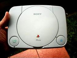
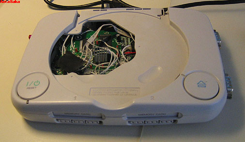
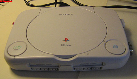
I have chosen a nice PSOne case for my C64DTV. It is small, nice looking, smooth and offer enough space to get all the stuff in I want to do. The PSOne may actually have been in working condition, but now I'll never know. It only cost me 8 bucks on eBay anyway. A few minutes with my trusty Dremel (or rather a cheap knock-off by Mannesmann) and the necessary openings and holes for 2x joystick, floppy and keyboard were done. Since I know my limits I did not plan for any special video or sound connectors.
After opening up the C64DTV case I was struck at first. I didn't realize before that the solder points where THAT small, especially the SMDs. First doubts about being able to actually solder this thing began to grow. Also my idea to have connectors which are screwed from the outside of the new case began to llok like a stupid idea since that mean I had to solder the whole thing inside the casing if I don't want to hide a fewt of extra cable later on. Luckily the solder points on the DTV2 can all be reached from the same side, so that minimized the problems a bit again.
For the cables for all the soldering I used an standard IDE cable which I split according to the needed connections. That way the cables that belonged together stayed together a bit better and I didn't lose the overview as fast as I expected. After each succesful test I fixated the solder points with a plstic glue gun. Otherwise I may have had to redo all solder points three times or so (yeah, I'm a bit clumsy).
As the first part the power connector was done, since I did not want to risk frying my keyboard with the +6V coming from the batteries (several websites mourned some losses). The connector was done about the same way as shown on this site. The power supply itself came from eBay. It was a leftover from a purchase done a month ago. It is part of an IDE-2-USB adapter package. However, I used a laptop hardrive so I didn't need the power supply. The reason to use this was that I knew it had +5V and GND right where I wanted it to be. I just needed to use a modified MOLEX plug from an old Pentium cooler. Click for a bigger picture.
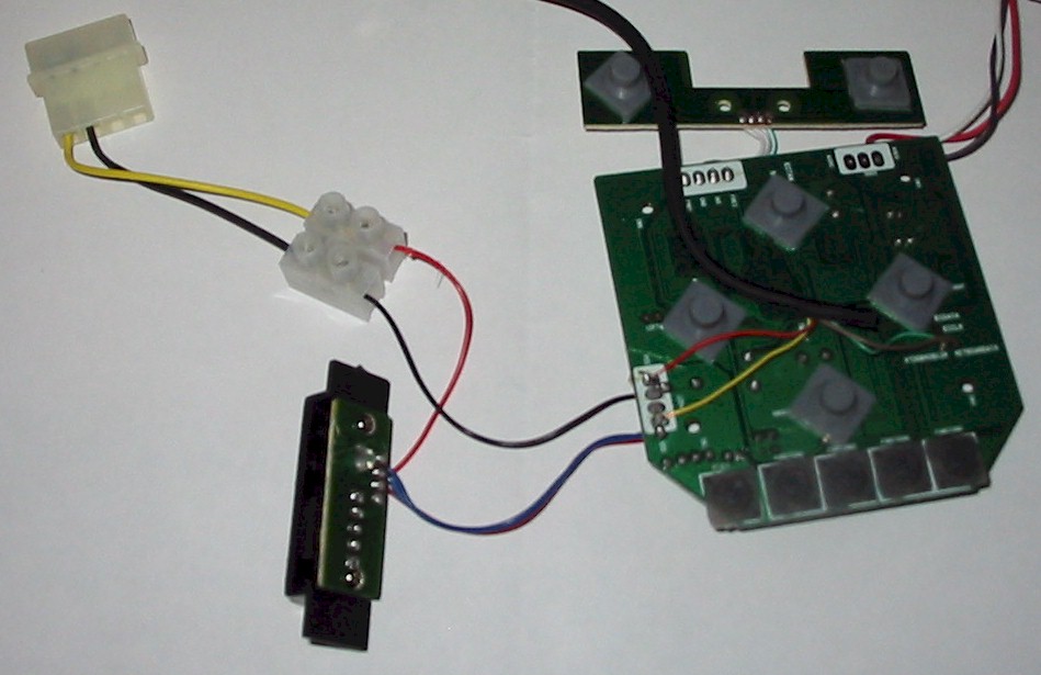
(Sources: Image 1, Image 2 and 3)
I had set myself to using the original PSOne power button to switch the C64DTV on and off. Therefor I needed to seperate the front part of the PSOne from the rest of the stuff. This also had the nice side effect of filling up the joypad slots again, so I did not need to think something up to make them nice again. The multimeter I bought for 5 bucks two days ago was a very good invest, as I ended up checking every solder point from here to the rest of the project at least three times each.Four solder points later all was well.
When I switch the thing off and on again I get a screen fuill of characters behaving weird (blinking etc. looks like a PAL error). After a RESET everything is fine. Update: It's all clear now: "It is also worth mentioning that the power switch cuts the ground, not the +5V as one might think. The reason is that there is a small resistor designed to drain any current from the capacitors on the board. The idea is that when you shut it off, the memory has to be dumped before you would be able to boot it back up properly. So the way the power switch is wired up is for that purpose." If you do not dump the memory the computer stays in an undefined state. The original C64 performed a Reset upon switch-on to avoid precisely that. This functionality has not been implemented in the C64DTV. Which means I have to do the Reset by hand if I don't want to abandon my power switch solution. Well, that's what the Reset-Button is for, I guess.
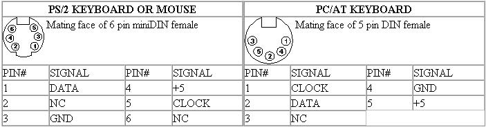
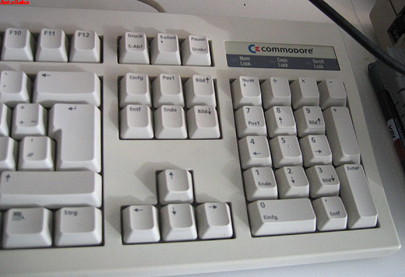
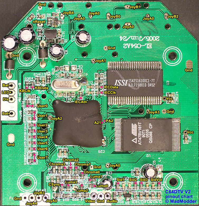
As the second thing, I attached the keyboard (just four solder points plus four in the connector). You can either use a PS/2 (6pin miniDIN) or AT (5pin DIN 180�) connector. I went with the AT connector, since I had a nice corresponding keyboard spare. You only need four of the lines (Clock, Data, +5V and Ground - marked as KBClk and KBData on the picture - grab any free GND and the +5V pin), ignore the ones marked as NC. Once again, these are the sockets as seen from the outside, not the solder pins.
I went for the AT connector since I rescued a nice Commodore keyboard from the trash two weeks ago. It fits nicely with the theme.
After plugging the keyboard in and running the first test I thought I did it all wrong. Even though I pressed the 'k' key on bootup no BASIC screen would appear. After a small panic attack (not the last one this weekend) I went browsing a bit more and found out that I had to use the 'CTRL/STRG' key instead. Presumably the 'k' key only works on the DTV1 or PS/2 keyboards, I don't know. But I was very relieved to see the old blue BASIC screen again.
Next up were the joystick connectors. I used two premade serial connectors (the ones that were used for serial mice back in the heydays of computering before the PS/2 connector came around). That way I saved myself from soldering 18 more spots. Sadly, not both of them were soldered the same way. One had a nice 1 to 9 soldering from the cables to the pins. However, the other had a one-up-one-down style of soldering, so cable 1 was pin 1, but cable 2 was pin 6 and so on (1-6-2-7-3-8-4-9-5). Luckily I noticed that early on and avoided problems that way.
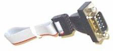
The socket itself is very basic serial Sub-D 9pin connector. Note that this is the connector socket as seen from the front (where you plug the cable in, not the side where you solder the cables, neither the connector coming from the joystick. Ignore POT-X and POT-Y. Yellow is Joy2 (the mainly used port), red is Joy1 (rarely used). Click for a bigger picture.
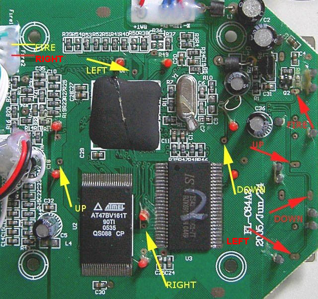
The first test was a disaster since I read the description on a website backwards. I was lucky though - nothing died and with a bit of resoldering everything was fine and Joy2 was working quite nicely. Then I soldered Joy1 'blind' meaning that I didn't have any program to test the functionality of it. Then I remembered that I had read somewhere about it. Sure enough I found a rather old C64 book ("C64 intern" by Data Becker) where I found a nice little program on page 78. The program is so small that it can be typed in quickly. Please note that you need to reset (hard or via STOP/RESTORE) to exit it.
Program to test the joysticks

10 POKE56322,224
20 J=PEEK(56320)    <--- for Joy2, for Joy1 you need to use 56321
30 IF(JAND1)=0THEN?"UP"
40 IF(JAND2)=0THEN?"DOWN"
50 IF(JAND4)=0THEN?"LEFT"
60 IF(JAND8)=0THEN?"RIGHT"
70 IF(JAND16)=0THEN?"FIRE"
80 GOTO20
Now I just need to connect the Floppy Drive and I'll be done (already 3 AM). And then it happened.. one of these dirty little SMD chips (the IECClk one) got too hot and removed itself from the layer. Of course. The last solder point of the whole project. This was so predictable. Well, after searching for a very small set of tweezers I managed to get the SMD back in place. This whole ordeal made it clear to me that I should not try to do the color-fix myself. I guess my hands are just to shaky. For the floppy drive we need a 6pin DIN 240� connector. Again we need four of the available pins (Clock, Attention, Data and Ground - marked as IECClk, IECAtn and IECData on the picture, grab any free GND), ignore the SRQ and the RESET line. And once again, this is the socket as seen from the outside, not the solder pins.
(Sources: Image 1 and 2, Image 3)
The first test with the Floppy Drive went quite well, once I remembered that I changed the drive address from 8 to 9 somewhen in the last 15 years (possibly to use it as a secondary drive on my C=128D). Once I found out it was quite easy and access (LOAD"$",9,1) was granted. Now I was done with the whole soldering and could finally go to bed and sleep a few hours.
Naw, forgot something. The RESET button didn't install itself either. I had ordered a simple button. All you need to do is solder one line to nReset (upper left hand corner of the picture) and the other to one of the last remaining free GNDs on the layer (there is one right above the reset line). OK, now that's the final one.
Just 36 solder points later...
The next morning. What is left to do? Ah yeah, the power connector needs to get into the casing as well. General clean-up phase begins, check if everything fits into the casing. Fits, great. And then realize that you forgot to drill the hole for the RESET button. Crap. So drill another hole, but careful not to get any stuff on the already installed parts. Finally done.
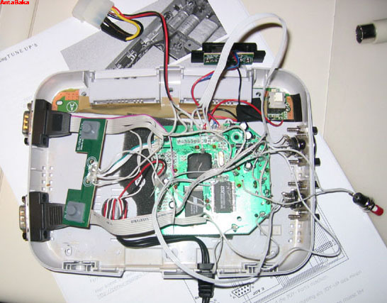
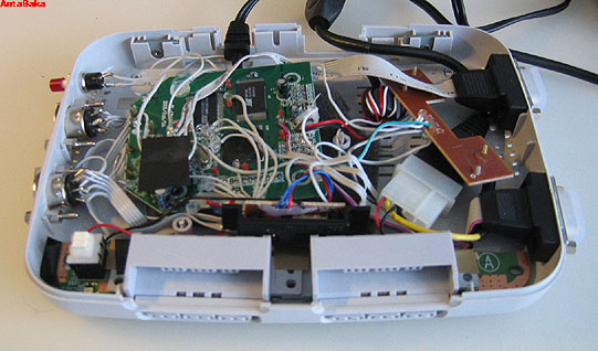
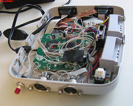
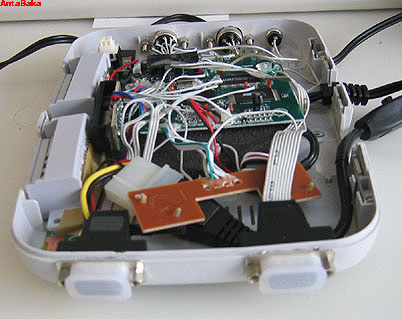
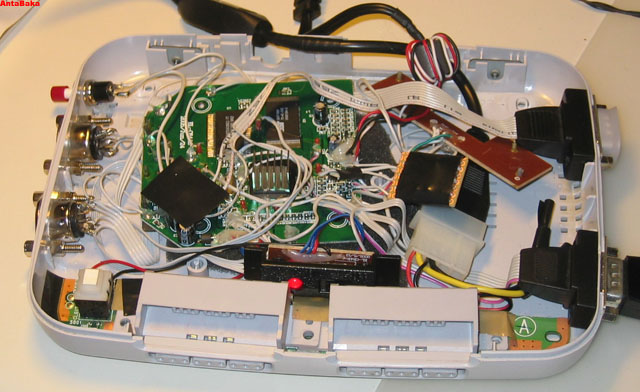
Here are a few pictures from above and the sides with the connectors.
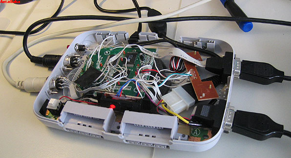
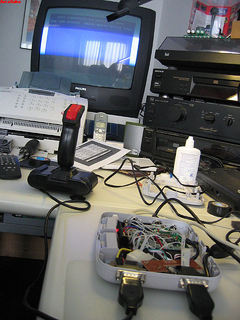
In the upper right hand corner you can see the (now empty) original casing of the C64DTV.
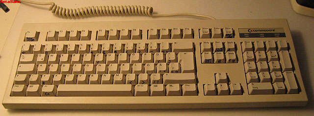
The keyboard with the C64 specific markings done in crappy handwriting style.
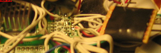
On this picture you can see that I applied a small heatsink on the ASIC. It just felt a bit hot somehow and I had some of these lying around.
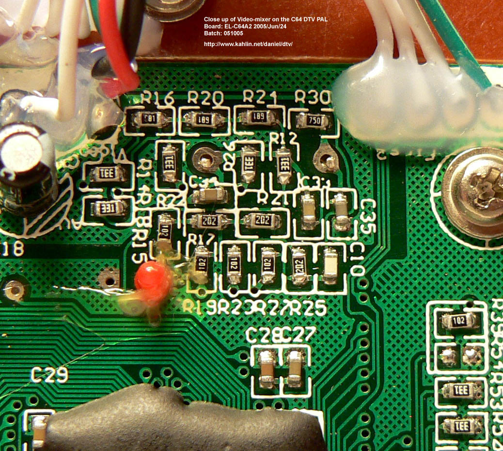
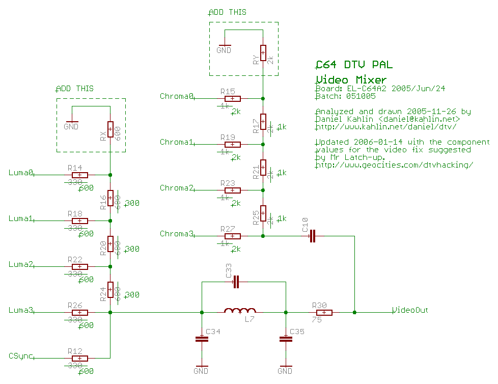
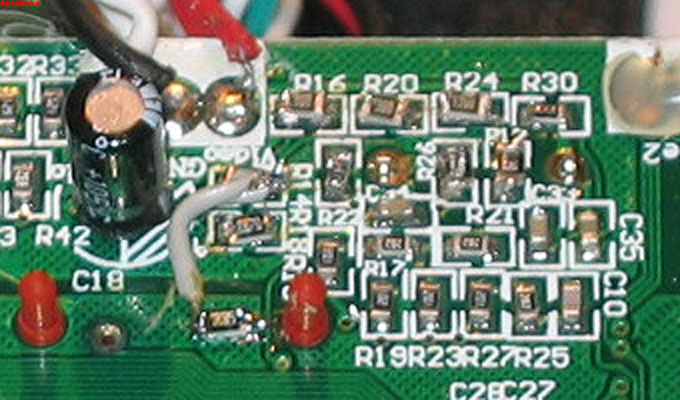
After a while I reconsidered my decision not to do a video signal fix. As is known by now and from the schematics, the chinese manufacturer accidentally switched the values for some resistors and omitted some others, probably to cut some more costs (a few cents per assembled unit I guess). A very detailed explanation can be found here. The botched resistors result in a quite bad video quality as can be seen on this and this page.
To solve the problem there are several solutions. All of which require soldering a few SMD components, something which I thoroughly dislike, probably Ibecause I don't have small enough tweezers to handle them. The complete video fix includes changing R12, R14, R18, R22 and R26 to 680, R16, R20 and R24 to 330 and adding a 680 resistor (RX) between R14 and R16 to ground, as well as changing R15, R19, R23 and R27 to 2k, R17, R21 and R25 to 1k and adding a 2k resistor (RY) between R15 and R17 to ground. This is all documented on the above mentioned pages. However, that is WAY to much SMD soldering for me. 17 Resistors need to be de-soldered and re-soldered. Naw, not for me.
(Sources: Image 1 and 2
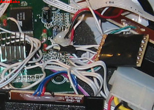
Luckily there is also a significantly easier fix available. It only requires to solder three 220 Ohm resistors in parallel with R16, R20 and R24 as well as adding a 330 Ohm resistor between R14 and R16 to ground. Well, only adding four resistors? I can do that. I had quite a few 200 Ohm resistors in my possession, although they weren't SMD style. Which meant mounting them on a piece of board and setting up wires. I did the same thing for the 330 Ohm resistor, even though that one actually was a SMD piece.
You can't really see much on these pictures unfortunately. Digital cameras, autofocus and me don't go well together.
I bought a quite cheap C64DTV2 PAL on ebay which was advertised as being defective. The reason for this was that "you are unable to enter the player names in three of the games (California, Summer and Winter Games). Well, that sounded to me like a problem with the joystick, namely the right contact. And yes, after opening the stick it became apparent: The right contact hat a constant-connection, thus screwing up some stuff. I put a small plastic ring under one of the plastic nipples and the stick worked finer again.
Since I already opened up the stick, I thought I might as well give the more complicated Luma-Fix a go. Which meant changing R12, R14, R18, R22 and R26 to 680 Ohm, R16, R20 and R24 to 330 Ohm and adding a 680 Ohm resistor (RX) between R14 and R16 to ground. I already ordered the SMD resistors (805er) when I started working on the PSone-DTV, but never used them. In the meantime however I felt much more secure working with the soldering iron.
Results: As expected the colors are more even with the pulldown resistor Rx (680 Ohm to GND). However, at the same time the overall color seems to be darker. The color combination White on Cyan (Summer Games, Winter Games and Impossible Mission) is therefore harder to read then without the Rx resistor. So I ultimately cut the connection that is shown on the picture again. Possibly the chroma-fix may rectify that problem, or maybe simply using different resistor values (300 instead of 330 Ohm and 600 instead of 680 Ohm).
Tip: To get fast into the DTVTEST5 program, for example to see this color palettem you need to perform a Reset and keep the Buttons A and D pressed until a white screen shows up. Release the buttons now and you are instantly in the DTVTEST5 program. Here you see the color palette, the memory is being checked and a checksum is calculated and also you can check the movement of the joystick and all the buttons on the device.
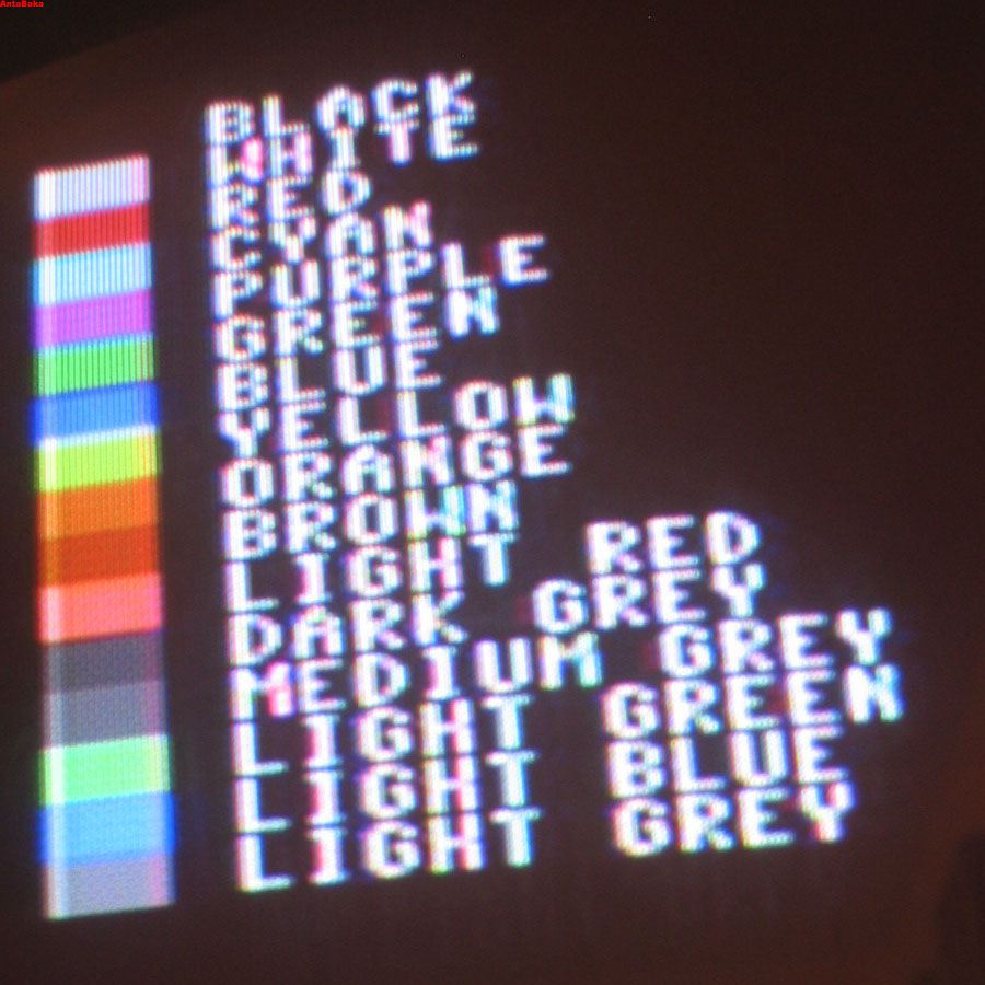
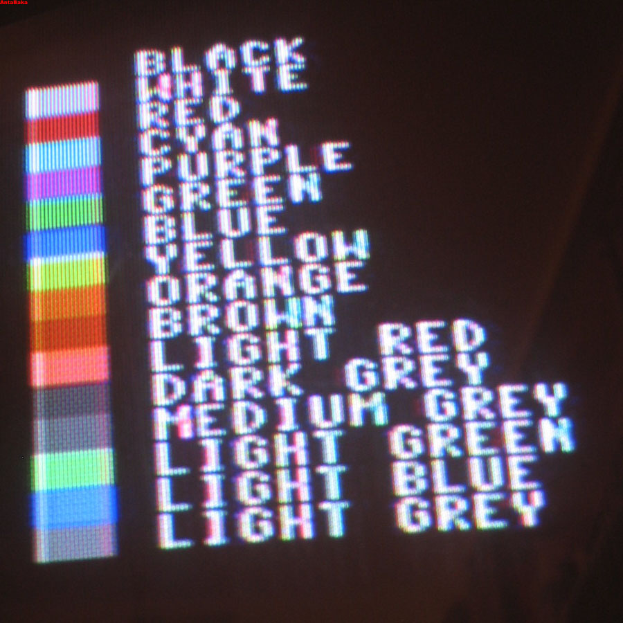
Bilder: Fix build in my system, colors with Rx (680 Ohm to GND) and without Rx.
(Sources: Own images)
These are the websites that helped me doing this.
Last update: 19.01.2007